In 2015, I got tasked with a new project for Dynobend. This has been one of my favourite projects at Sioux (still LIME in 2015), so I figured it would be nice to write something about it.
Dynobend is a company of about 50-100 people, located in Haaksbergen and manufacturer of bending machines: Machines that take in straight metal pipes and bend them into all kinds of curved shapes. Words don’t really do these machines any justice…
The freeform machines push the pipe through some rollers which can be purposely misaligned to impart some curvature (plastic deformation) to the metal pipe. The pushing rod moreover can twist, which unlocks the third dimension for 3D freeform shapes.
Equally impressive as the mechanism of these machines, is the wide range of applications these freeform tubes have, from stair lifts, to designer furniture, to spinal implants, to heat exchanger tubing to facades in high-end architecture.
The very first project LIME did for Dynobend happened before I joined LIME, and was about setpoint generation for this pushing rod/cart. To achieve a high throughput of the machine (= bend a shape as quickly as possible), you want to move the pushing cart as fast as possible. However, when the rolls are severely misaligned, as to impart a high curvature, the forces when moving the cart fast just become too big to handle. So, like a racecar, sharp curves are to be taken more slowly, straight sections can be taken full speed. A very nice mathematical challenge, and even a pity I never got to solve it myself. Setpoint generation problems are some of my favourite, and luckily I do have a few more on my track record by now.
The challenge that Dynobend gave to us in 2015, was about ‘shape control’. They already had a way to calibrate the machines, but when bending complex 3D shapes, the shapes still weren’t coming out quite right. The mismatch between target and result could already be quantified, by dimensional metrology tooling such as the AICON (now Hexagon) TubeInspect measurement cabinets.
The TubeInspect itself is already a very cool demo of applied mathematics and computer vision.
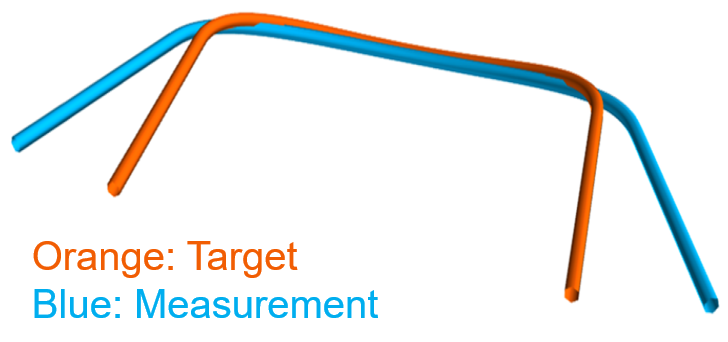
The figure below shows an example of a target shape (in blue) and an uncorrected measured shape (from an uncalibrated machine, for demonstration purposes) in orange. Typical shape errors we quantified in some millimeter unit, and the errors typically were about 10-20 millimeters. The example shown was even as big as 50mm (due to intentionally not calibrating).
However, knowing you’re wrong is only worth so much. What Dynobend was really looking for is a way to correct for the bending errors and reduce the shape error. Being mostly a mechanics-oriented company, they didn’t have the necessary mathematical skills in house, and multiple people had already tried and failed on correction of 3D shapes. Luckily, they found us :)
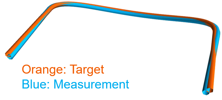
One of the reasons this has been one of my favourite projects, is because of the good results. Through our mathematics, we have been able to, typically, drive down the shape error from 10-20mm to 1-2mm, for a whopping 10x improvement! Moreover, this is generally achieved in 1-2 iterations of bending and correcting. In fact, even the exagerated case above, with the >50mm initial error could be brought down to 2mm in a single iteration. The correction approach can largely make calibrating unnecessary. Below is the corresponding visualization of the measurement of the bent tube obtained from a corrected shapefile.
The shape correction approach has been wrapped by Dynobend into a product called the ‘Dynobend Tube Optimizer’ (DTO), which has been introduced at the huge German ‘Tube and Wire’ fair in 2018.
If you want to the bending and correction process in action in real-time, you can check out the DTO webinar on the Dynobend YouTube channel.
Finally, other reasons for liking the project are the tangibility off it all. I have worked many years for ASML without ever seeing a real EUV scanner up close. With Dynobend, I can modify a line of code, and see what it does to a metal pipe in a matter of minutes. Secondly, I enjoyed very much that there was a blank sheet to start from. Comparing to ASML again, there one usually improves one particular method that other smart have already preceded you on. Here, everything had to be started from scratch, and a lot of different pieces of applied mathematics had to be stitched together to get the complete pipeline working. Inevitably, computational geometry and the especially the mathematics describing 3D curves apply, as in previous post on the Matrix logarithm of rotational matrices. Unfortunately, that is about as much as I can tell about the solution. Dynobend considers it important intellectual property, which is being protected through secrecy rather than patents.
Related posts
Want to leave a comment?
Very interested in your comments but still figuring out the most suited approach to this. For now, feel free to send me an email.